STA mode is a common way to configure WIFI, there are many tutorials on the Internet, the following wpa_cli as an example
Enter the dedicated console and select wlan0 by default
The new firmware optimizes the joint calibration accuracy. The previous calibration accuracy does not meet the requirements and needs to be re-calibrated.
When the device is configuring the network, the network WiFi configuration fails.
This problem is related to the wireless environment, especially when the exhibition and other places, the wireless environment is more complex, more interference. You can take the G1 device to a place with less interference and try a network configuration.
G1-29 DOF device, after unlocking the waist fixator (APP synchronously closes the waist lock switch), report the joint out-of-limit position error.
If you decide not to use a personal backup system image for recovery, you can download the factory system image provided by Unitree Technology through the following link:
After flashing the system, there may be cases where the recognized disk capacity appears smaller than expected. You can use the following method to expand the disk.
Launch the GParted tool by executing the following command:
sudo gparted
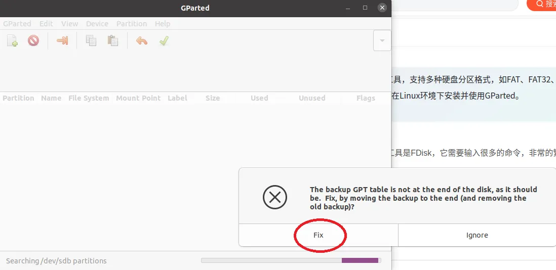
In the pop-up dialog box, select the fix option as shown in the image below:
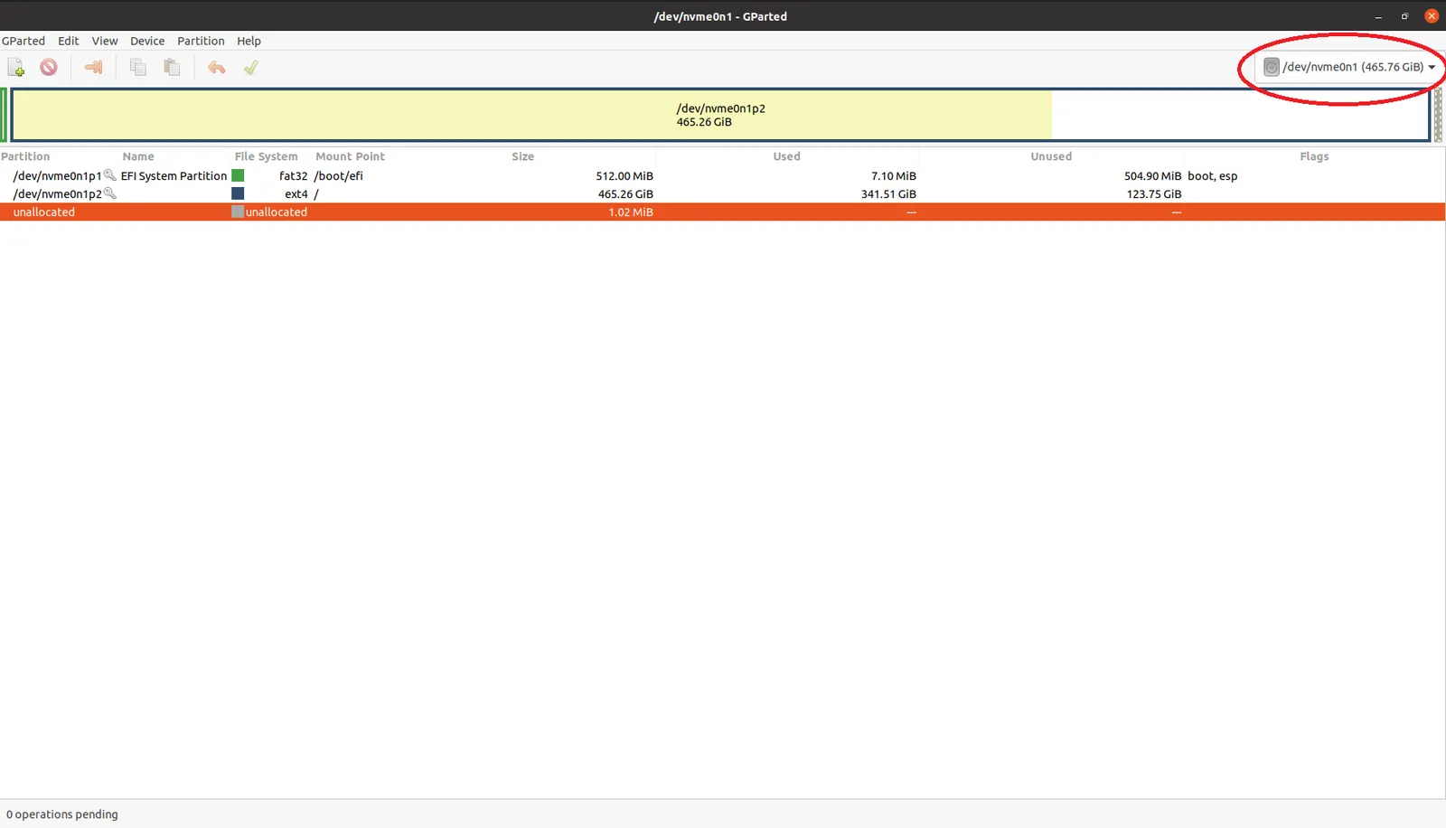
Once inside the GParted interface, click on the upper right corner to switch to the target disk (choose the disk where the G1 system has been flashed), as shown below:
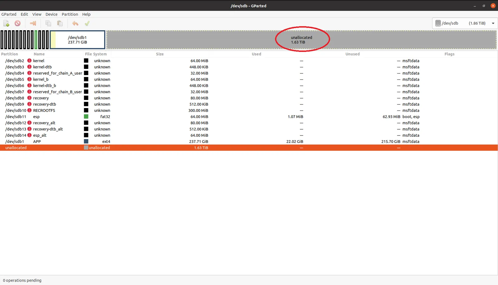
After switching disks, you will see the unallocated space on the disk, as shown below:
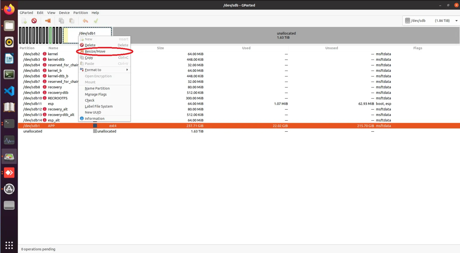
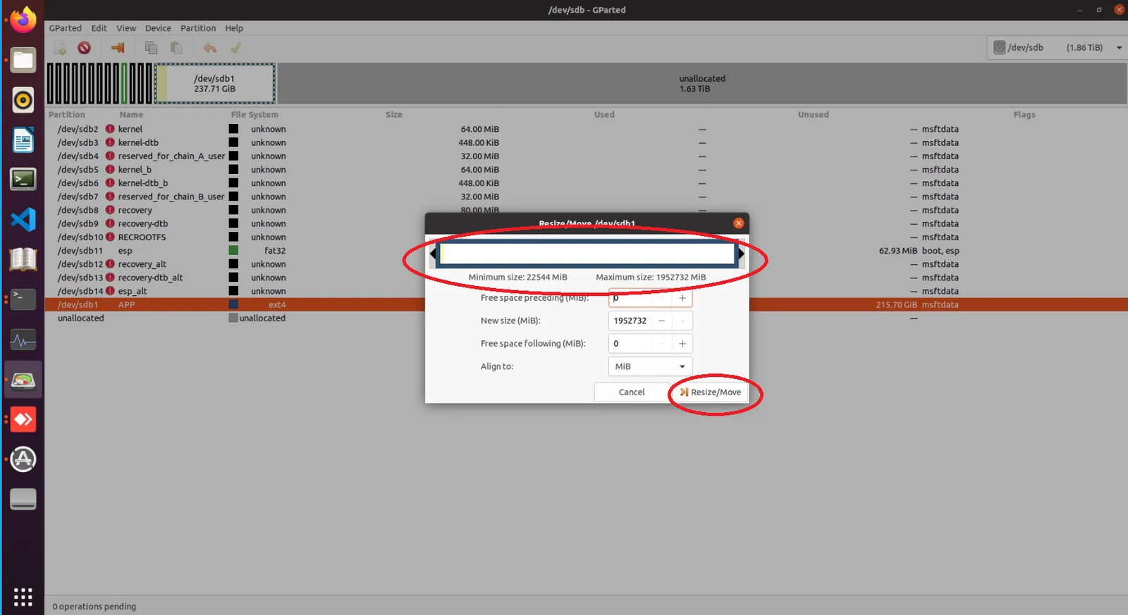
Right-click on/dev/sdb1,and chooseResize/Move, as shown below:
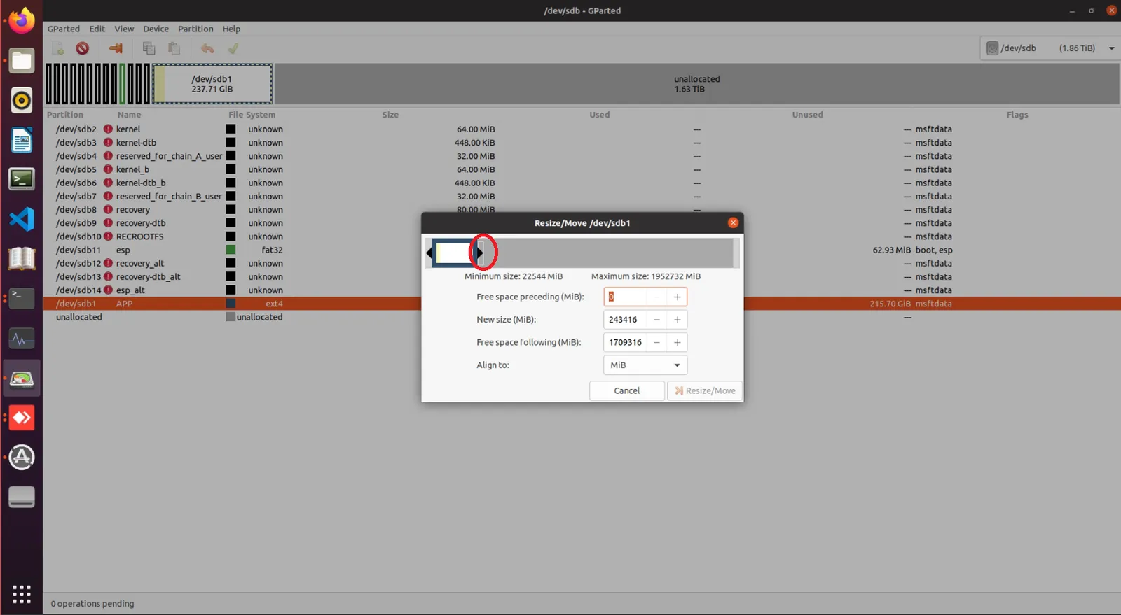
Drag the red area shown in the figure below to the bottom using the left mouse button, as shown in the image:
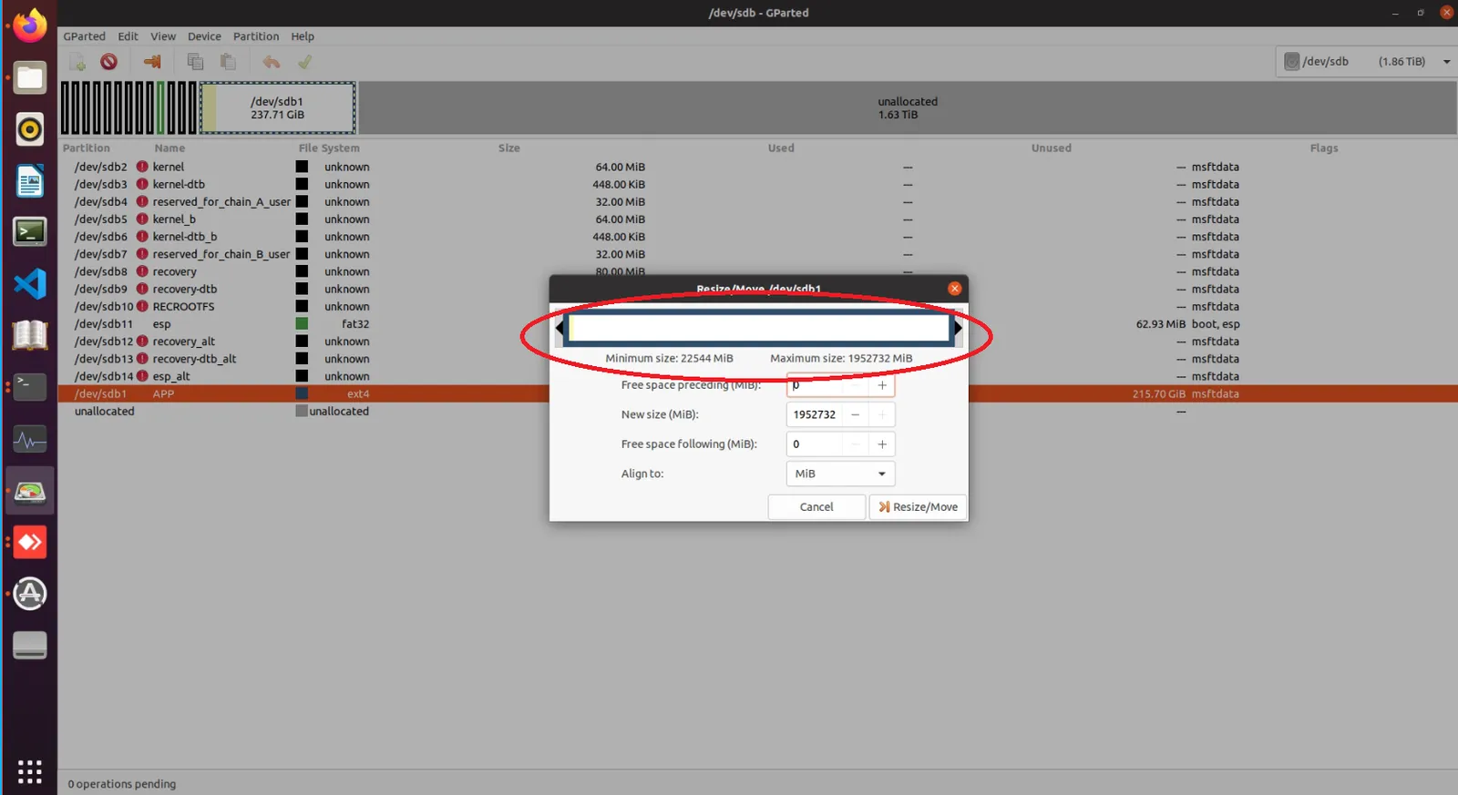
After dragging, the interface will appear as shown below:
Click theResize/Movebutton, as shown below:
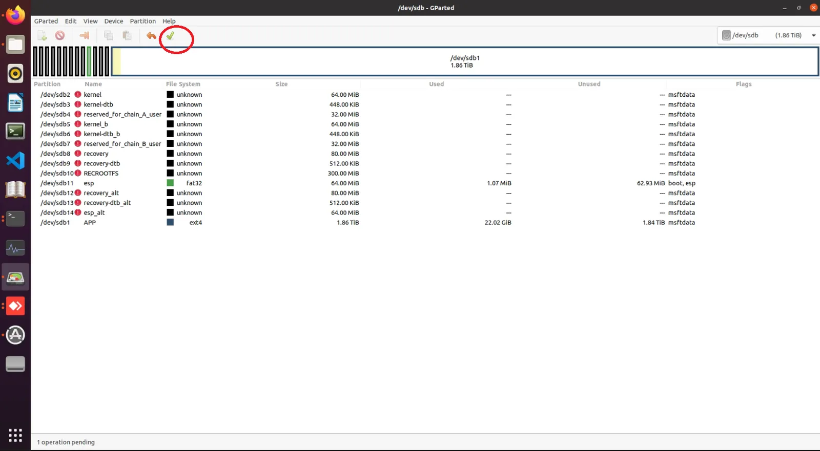
After the new window appears, click the checkmark icon to apply changes, as shown below:
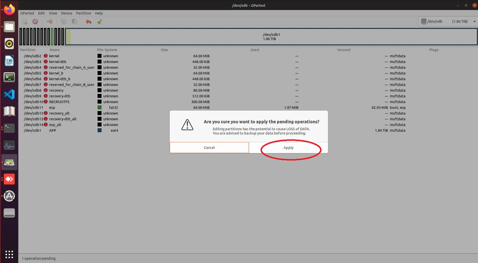
In the next window, click the Apply button, as shown below:
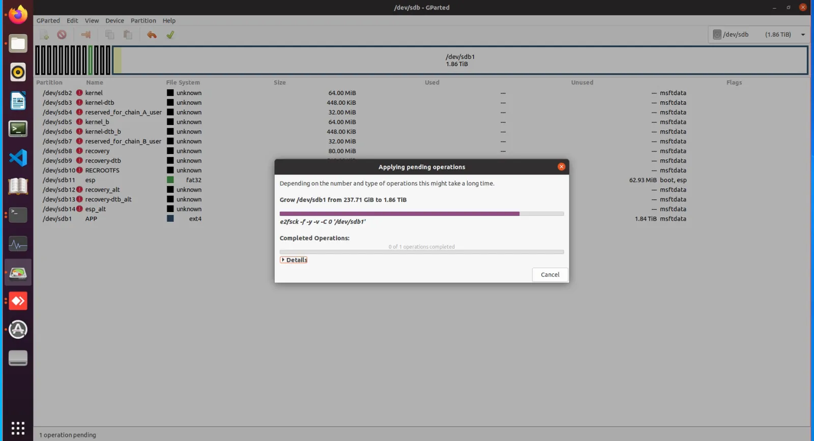
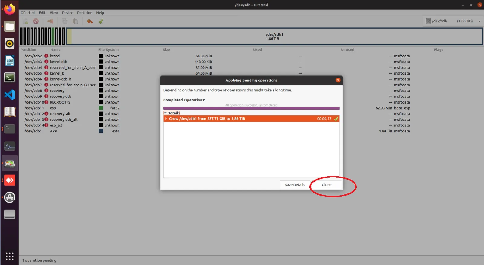
Wait for the operation to complete, as shown below:
Once completed, click the Close button, as shown below:
At this point, the disk expansion process for G1 is complete. You can now safely eject the disk from your PC and install it into the G1 device for normal usage.
Method for Enabling WiFi After System Recovery on Jetson Orin NX
Note: The g1_nx_Jetpack5.1.1_20250930.img.bz2 image already includes built-in Wi-Fi support; after flashing, there is no need to use this method to enable Wi-Fi.
Use the following commands to install the necessary software tools:
Download the WiFi drive .deb package:
WIFI Driver Package
After downloading and extracting the file, you will find a file named rtl8852bu-dkms_1.19.14_arm64.deb .
Execute the following command to install the driver:
sudo dpkg -i ./rtl8852bu-dkms_1.19.14_arm64.deb
Note: The installation of the WiFi driver may take a while, please wait patiently. It usually takes around 20~30 minutes. To monitor its progress, you can use the following command:
This is caused by missing essential patch files on the NX board. To resolve this, upgrade the NX board with the required patch files using the following steps:
Serial port parameters: Baud rate 9600, 8 data bits, no parity, 1 stop bit.
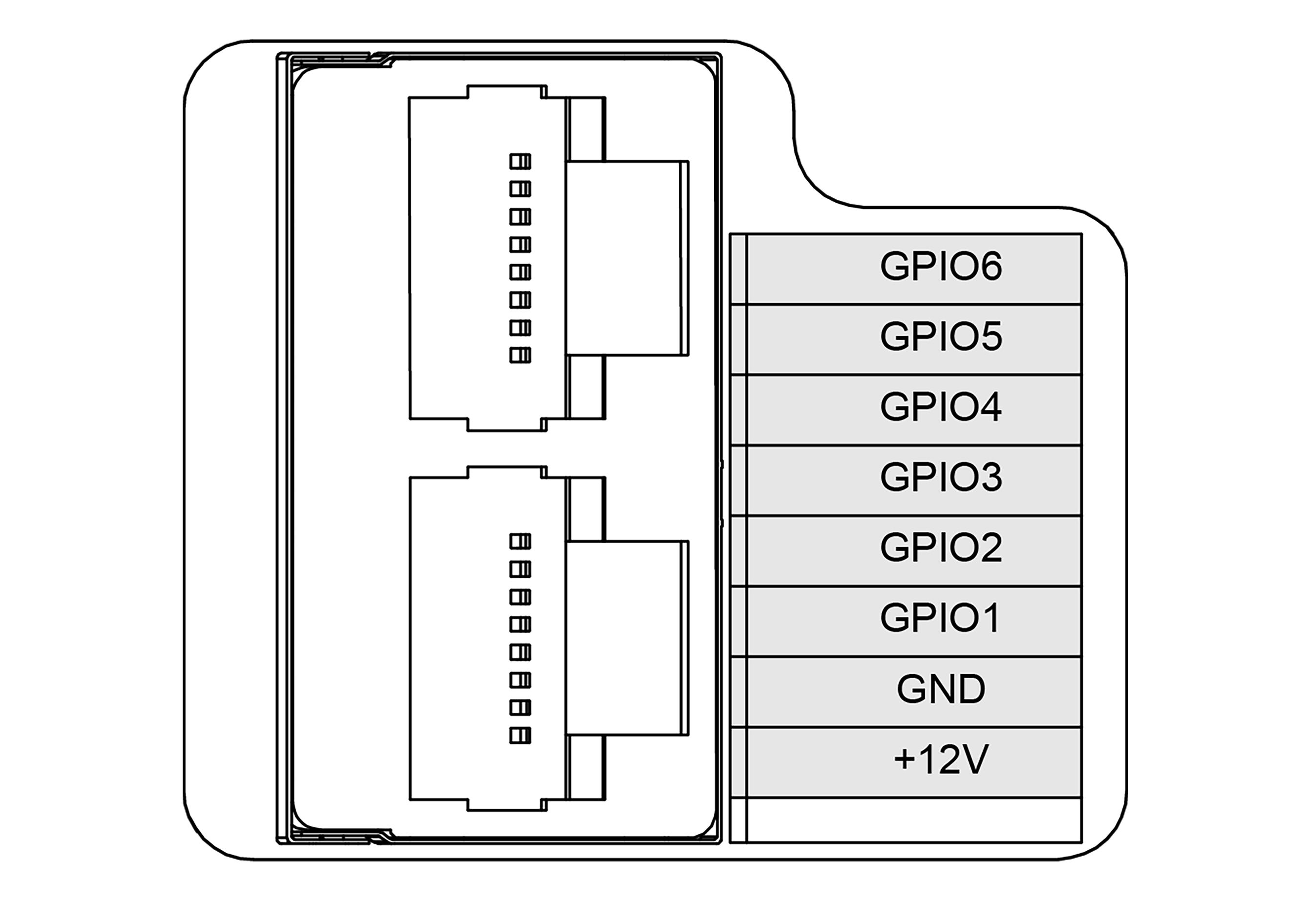
After the G1 system starts, GPIO1 and GPIO2 are configured for UART functionality. They can be used simply with the following methods:
After the G1 system starts, GPIO3 and GPIO4 are configured for I2C functionality.
When an I2C device is connected to the corresponding pins, the following command can be used to detect the device:
The mapping relationship for G1’s GPIO in Libgpiod is:
GPIO
sysfs
Libgpiod
GPIO5
PCC.02
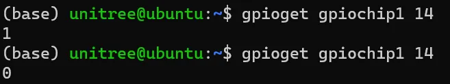
gpiochip 1 14
GPIO6
PCC.03
gpiochip 1 15
The G1 has two GPIO chips in total. GPIO5 and GPIO6 are on chip 1, while the others are on chip 0. Use gpiodetect to view the current number of chips and their names, and use gpioinfo [chip number] to view the IO port mapping names and status for the corresponding chip.
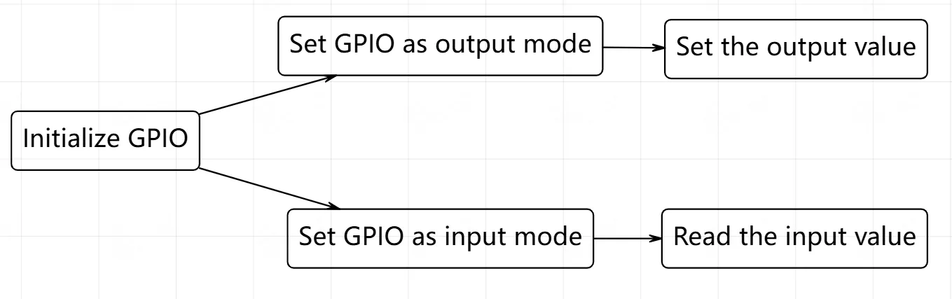
Libgpiod automatically handles the enable state. Use the command gpioset gpiochip[chip number] [pin mapping number]=[level] to set the GPIO pin to output mode and specify the level.
Libgpiod automatically handles the enable state. Use the command gpioget gpiochip[chip number] [pin mapping number] to set the GPIO pin to input mode and read the level.